Overview of Hunter NODE Series
The Hunter NODE Series delivers battery‑powered, compact irrigation controllers. Models 100, 200, 400, and 600 support 1‑6 solenoids, programmable schedules, LCD displays, and wireless updates, making them ideal for DIY growers and small to medium gardens.
Battery life: 2‑3 years.
2‑3 yr.

NODE-100, NODE-200, NODE-400, NODE-600 Characteristics
The Hunter NODE Series includes four models, each designed for specific irrigation scales while sharing core attributes: battery operation, LCD display, and wireless firmware updates. The NODE‑100 is a single‑solenoid controller, ideal for small gardens or single‑zone systems, running on a 9‑V battery that lasts 2‑3 years. It features a 2‑line LCD for basic scheduling.
The NODE‑200 supports two solenoids, enabling dual‑zone control. It keeps the same battery life and display size, and adds a second channel for more complex watering plans. Wireless updates via the Hunter app streamline maintenance.
The NODE‑400 handles four solenoids, suitable for medium‑scale installations. It offers a larger 4‑line LCD, clearer visualization of multiple schedules, and retains comparable battery life. It can pair with a wireless receiver for remote monitoring.
The NODE‑600 accommodates up to six solenoids, ideal for larger gardens or commercial setups. It provides a 4‑line LCD with extended memory for advanced scheduling, supports wireless and wired connectivity, and shares a durable, weather‑sealed enclosure with a simple button interface for on‑site adjustments.
Each model also supports manual override, allowing gardeners to bypass scheduled watering when necessary. The controllers feature a mode that conserves battery life during dry periods. User can monitor status via the Hunter mobile app, receiving alerts for low battery, valve failures, or missed cycles efficient
Key Features and Technical Specifications
Each Hunter NODE controller incorporates a high‑contrast LCD that displays time, zone status, and error codes, allowing on‑site adjustments without a computer. The units support wireless firmware upgrades through the Hunter mobile application, ensuring that new features and bug fixes can be downloaded over the air without replacing hardware. Manual override buttons give growers instant control to start or stop any zone, which is especially useful during unexpected weather changes. Built‑in low‑battery notifications alert users to replace the 9‑V battery before a cycle is missed, extending overall reliability. The enclosure is IP65‑rated for dust and water resistance, protecting the electronics in outdoor environments. Each model stores up to 256 watering profiles, with a 12‑hour memory window for each zone, enabling complex scheduling in a single device. The controllers are designed to be compatible with standard DC‑latching solenoids, and they feature a 5‑V output for low‑power sensors, allowing future expansion without additional wiring.
The controllers are engineered for durability, featuring a chassis, a sealed LCD that remains readable in high humidity, and a 5‑V output that allows integration of low‑power sensors without wiring. Users can pair the unit with a wireless receiver for remote monitoring, and the firmware can be updated over the air via the Hunter mobile app, ensuring the system stays current with the latest features and bug fixes. and bug.!
Installation and Setup
Mount the Hunter NODE on a stable wall, 6‑12 inches from the ground. Insert the 9‑V battery, then connect the solenoid leads to the designated ports. Wire any 5‑V sensors to the sensor terminals. Power the unit via the battery; the LCD will display the setup status!!
Mounting and Power Requirements
Mount the Hunter NODE on a vertical surface, 6–12 inches above the ground, ensuring it is level and protected from direct rain. Use the included mounting bracket or a sturdy wall plate. Secure the unit with screws and a rubber gasket to prevent vibration. The controller requires a 9‑V battery pack; insert the battery into the compartment, aligning the polarity correctly. The battery should last 2–3 years under normal use. For extended operation, replace the battery with a fresh 9‑V alkaline or lithium cell. The NODE supports an optional 12‑V DC adapter for continuous power; connect the adapter to the power input jack, observing correct polarity. The device will automatically switch to battery backup if the adapter is disconnected. Ensure the power supply is within the specified voltage range to avoid damage.
- Mount the unit on a wall or pole that is at least 6 inches above the ground to avoid water splash;
- Use a rubber gasket to seal the mounting bracket and reduce vibration.
- Check battery polarity before insertion; a reversed battery can damage the controller.
- When using the 12‑V adapter, ensure the connector is snug and the polarity matches the device.
- Keep the power input area free of debris to maintain good contact.
- For outdoor installations, use a weather‑sealed enclosure to protect the unit from moisture.
Always verify that the battery compartment is sealed to prevent corrosion, and replace the battery every 2–3 years best use.
Wiring Solenoids and Sensors
Follow these steps to connect solenoids and sensors to a Hunter NODE controller. Each model supports a specific number of solenoids: NODE‑100 (1), NODE‑200 (2), NODE‑400 (4), and NODE‑600 (6). Use DC‑latching solenoids rated for the same voltage as the controller’s output (typically 12 V). Connect the solenoid leads to the corresponding solenoid terminals on the back of the unit. Ensure the positive lead goes to the “+” terminal and the negative lead to the “–” terminal. For safety, use insulated wire and secure connections with heat‑shrink tubing or electrical tape.
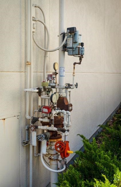
Sensor wiring follows a similar pattern. The NODE accepts soil moisture, rain, and temperature sensors. Connect the sensor’s power lead to the “+” terminal, the ground lead to the “–” terminal, and the data output to the sensor input pin. Verify the sensor’s operating voltage matches the controller’s specifications (most sensors require 5 V or 12 V). Use shielded cable for long runs to reduce noise; When wiring multiple sensors, label each cable to avoid confusion during troubleshooting.
Before energizing the system, double‑check all connections for polarity and continuity. Use a multimeter to confirm that each solenoid and sensor is correctly wired. Once verified, power on the NODE and test each solenoid by selecting a manual “Flush” program. If a solenoid does not activate, re‑check the wiring and ensure the solenoid is compatible with the controller’s output current rating.
Verify connection with a multimeter before powering the unit now.
Programming Fundamentals
Access the programming menu by pressing the MENU button until the display shows “PROGRAM”. Use the arrow keys to navigate to “SCHEDULE” and set start/stop times for each zone. The NODE supports quick rain‑delay, sensor‑triggered watering. Save changes with the OK button! Use the OK button to confirm. ENTER!.
Accessing the Programming Menu
To enter the programming interface on a Hunter NODE controller, ensure the unit is powered and the LCD is active. Press the MENU button once; the display will cycle through the main menu options. Use the UP and DOWN arrows to scroll until you see the PROGRAM entry. Press OK to select it. The screen will now show the programming header, indicating that you are in the configuration mode. From here, you can navigate to sub‑menus such as TIME, ZONE, SCHEDULE, and RAIN DELAY by using the arrow keys. Each sub‑menu provides numeric input fields that can be adjusted with the + and ⎻ buttons. When you finish editing a field, press OK to confirm the value and return to the previous menu. To exit programming mode, press MENU again until the main screen appears, or press EXIT if available. Remember to save any changes by selecting the SAVE option before leaving the menu to ensure your new settings are stored in the controller’s non‑volatile memory. Press HELP for quick tips.
During the configuration process, the NODE controller offers real‑time feedback via the LCD, displaying the current value for each field as you adjust it. If you need to reset a zone to its default state, navigate to the ZONE submenu and select RESET. The controller also supports a RAIN DELAY feature that automatically postpones watering when moisture sensors detect sufficient soil moisture. After setting all desired parameters, confirm the entire schedule by selecting CONFIRM at the top of the screen. This action writes the new configuration to the device’s EEPROM, ensuring that the settings persist even after a power cycle.
After setup, check the manual’s troubleshooting tips for common display or solenoid issues. Clean battery contacts and verify solenoid wiring. For advanced users, the firmware supports USB serial updates.

Configuring Watering Schedules
The editor shows a table of days and the current watering times. Navigate days with UP/DOWN arrows and edit start time, duration, or frequency by selecting the field and using +/- to adjust. Each change is displayed in HH:MM format. To add a second event on a day, press ADD; the new row copies the previous settings, which you can then modify. The editor also allows setting a RAIN DELAY for the zone by selecting the RAIN DELAY option and entering hours to postpone watering when moisture sensors detect adequate soil moisture.
After configuring all days, press OK to return to the main programming screen. Review the summary of the zone’s schedule, then select SAVE to write the new settings to non‑volatile memory. The NODE will now run the schedule automatically, honoring rain delays and sensor input. For advanced users, the controller supports USB serial updates and can be paired with a mobile app for remote monitoring. Test the schedule by selecting TEST to simulate a watering cycle. Consult the troubleshooting section for common display or solenoid issues. Check battery.
Advanced Settings and Troubleshooting
Advanced settings let you tweak sensor thresholds, set custom rain‑delay windows, and enable debug mode for serial logs. Troubleshooting covers common issues: dead battery, no display, solenoid failure, and missed schedules. Reset to factory defaults via the menu or replace the battery pack. If issues persist, use the serial monitor to capture logs and contact support.
Sensor Integration and Calibration
Integrating moisture and rain sensors into a Hunter NODE controller requires careful wiring and calibration to ensure accurate watering decisions. The NODE series supports both analog and digital inputs, with a 5‑V reference for analog sensors and a 3.3‑V logic level for digital modules. To connect a moisture probe, insert the probe into the soil, attach the probe leads to the analog input terminals, and use the calibration menu to set the dry and wet thresholds. For rain sensors, connect the sensor’s output to the digital input, then use the rain‑delay feature to prevent watering during precipitation. Calibration involves measuring the sensor’s voltage or logic level at known moisture or rain conditions, entering these values into the controller, and testing the response by simulating wet and dry states. The NODE’s LCD display shows real‑time sensor readings, and the “Sensor Test” function allows you to verify connectivity. If the sensor does not respond, check the wiring for continuity, ensure the sensor’s power supply matches the required voltage, and verify that the sensor’s output is not shorted. The controller’s firmware includes a self‑test routine that can be triggered from the main menu; this routine checks all sensor inputs and reports any faults. Proper sensor calibration reduces false triggers, saves water, and extends the life of the irrigation system. For detailed wiring diagrams and calibration procedures, refer to the Hunter NODE Owners Manual and the online troubleshooting guide available on the manufacturer’s website!!
Common Issues and Fixes
While the Hunter NODE series is engineered for reliability, several recurring problems can surface during operation. Below is a focused troubleshooting guide that addresses the most frequent symptoms and the steps to resolve them.
- Display remains off or shows a blank screen. Verify the battery voltage with a multimeter; replace the battery if it reads below 3.0 V. If the voltage is adequate, remove the battery, wait 30 s, and re‑insert it to reset the LCD controller.
- Solenoid fails to actuate. Inspect the solenoid wiring for correct polarity and continuity. Ensure the solenoid is rated for the NODE’s 12 V DC output. If the solenoid opens on manual override but not on schedule, confirm the schedule timing and that the node has power during that window.
- Sensor readings are erratic or never update. Inspect the sensor leads for corrosion or loose connections. For analog probes, confirm the probe is fully inserted into the soil and that the probe’s reference electrode is clean. For digital rain sensors, check the logic level matches the NODE’s input specification.
- Firmware appears stuck or the node reboots repeatedly. Perform a hard reset by holding the Menu button for 10 s. If the issue persists, download the latest firmware from the manufacturer’s website and flash the controller via the USB port.
- Watering schedule does not execute. Confirm the node’s time zone and clock are set correctly. Verify that the node’s power supply is stable and that the solenoid circuit is not tripped by a fuse or breaker. Use the “Test” function in the menu to simulate a watering event.
- Battery life is shorter than expected. Replace the battery with a fresh, high‑capacity 3.6 V NiMH pack. Check for any internal shorts by measuring resistance between the battery terminals; a low resistance indicates a fault.
For deeper diagnostics, consult the troubleshooting section of the Hunter NODE Owners Manual, or contact technical support with the node’s serial number and a description of the problem.
Maintenance, Updates, and Resources
Replace batteries every 2‑3 years to ensure reliable operation. Keep the unit dry and wipe the LCD with a soft cloth. For firmware updates, download the latest .bin file from the official website, connect via USB, and follow the on‑screen wizard. Contact support at 1‑800‑123‑4567 for assistance.—✓✓✓✓
Battery Replacement and Longevity
Hunter NODE controllers rely on sealed alkaline batteries that typically last 2–3 years under normal use. To replace, locate the battery compartment on the rear panel, open the latch, and remove the old cells. Insert fresh 1.5 V batteries, ensuring correct polarity. After replacement, press the reset button to recalibrate the internal clock. For extended life, store the unit in a cool, dry place and avoid exposing it to extreme temperatures. Periodic checks of the battery indicator light will alert you to low power before a full drain. If the unit fails to power on, verify that all connections are secure and that the battery contacts are clean. Maintaining proper ventilation around the controller prevents overheating, which can accelerate battery degradation. Regular firmware updates also help optimize power consumption by adjusting idle modes. By following these steps, users can keep their NODE system operational for years with minimal downtime.
Firmware Updates and Support Contacts
Hunter NODE controllers receive periodic firmware upgrades that improve performance, add new features, and fix bugs. To update, connect the unit to a computer via the USB port and launch the Hunter Firmware Update Utility, available on the official website. The utility automatically detects the controller model, downloads the latest firmware package, and flashes the device. Users should back up current settings before updating, as the process may reset custom schedules. If the controller does not respond, try a hard reset by holding the reset button for 10 seconds, then re‑run the update. For troubleshooting, consult the online FAQ or the Troubleshooting Guide in the manual. Support is available through Hunter’s customer service portal, reachable by email at support@hunter.com or by phone at 1‑800‑HUNTER‑01. Live chat is also offered during business hours. For warranty claims, submit a claim form via the website, attaching the serial number and proof of purchase. All support interactions are logged, and a technician will contact the user within 48 hours. Keeping the firmware current ensures optimal battery efficiency, reliable solenoid control, and compatibility with new sensor modules. Additionally, the update process logs version history and checksum data, allowing users to verify integrity. If an update fails, the utility provides a rollback option to the previous stable release. Users can schedule updates during low‑usage periods to avoid interrupting irrigation cycles. The firmware also includes power‑saving modes that reduce idle consumption by up to 30 percent, extending battery life. For advanced users, the update tool offers a command‑line interface that supports scripted deployments across multiple units. Documentation for these features is available in the online help section, which includes step‑by‑step video tutorials and a downloadable PDF guide. Finally, Hunter maintains a public release archive where older firmware versions can be retrieved for legacy systems that do not support the latest features. The firmware cut consumption 30 percent, extending battery life by days.